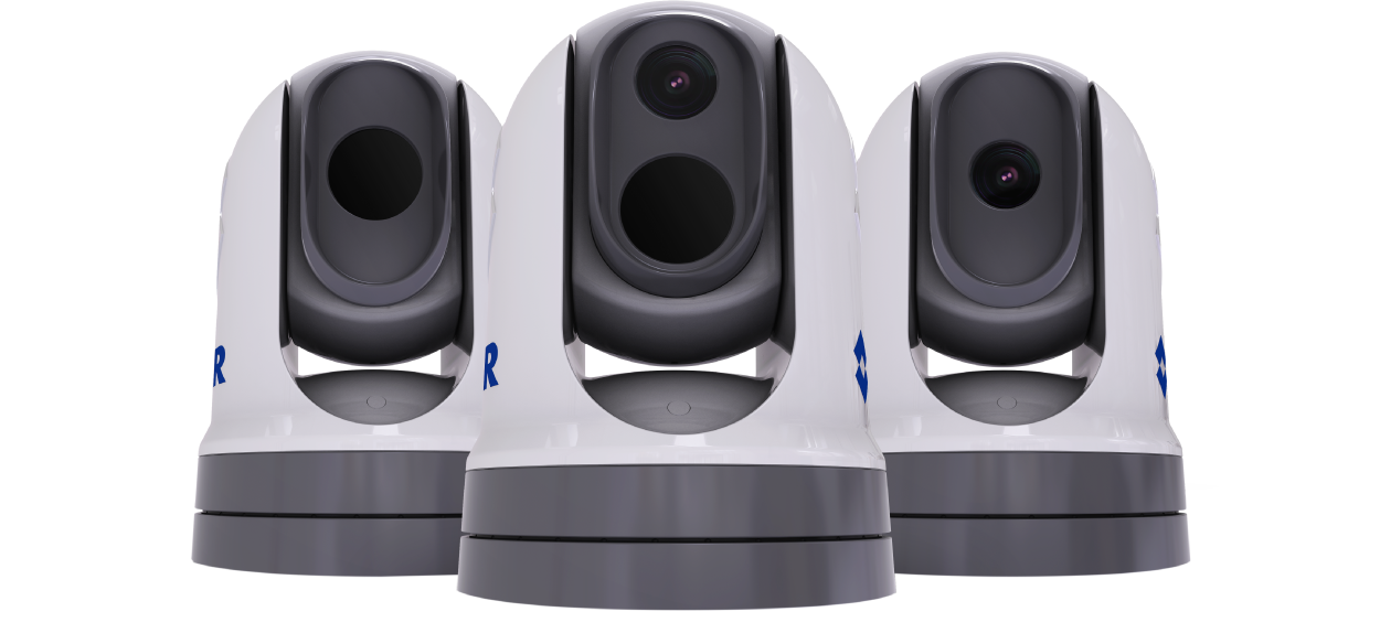
M300-Series Thermal Camera Installation & Operation Instructions
Let’s Go!
How to navigate this document
Legal notices (FLIR)
Patents notice
Export control
Important information
Safety warnings
Product installation and operation
Potential ignition source
Switch off power supply
Entrapment hazard
Ensure safe navigation
Maintain a permanent watch
Product warnings
Product grounding
Positive ground systems
Power supply voltage
PoE isolation coupler
Corrosion
Power supply protection
Service and maintenance
Regulatory notices
Cleaning the camera
Routine camera inspections
Water ingress
Disclaimer
EMC installation guidelines
Connections to other equipment
Declaration of Conformity
PSTI Compliance
Product disposal
Warranty policy and registration
Technical accuracy
Publication copyright
Document information
Document information
Applicable products
Additional system components
Product documentation
MFD / chartplotter software version
Applicable software version
Product and system overview
Product overview
M300-Series (single payload)
M300-Series (dual payload)
System overview
Control options
Display options
Compatible Joystick Control Units (JCUs)
Compatible MFDs / chartplotters
Parts supplied
Parts supplied
Product dimensions
Product dimensions
M300 Series
M300 Series with optional mounting riser
Location requirements
Warnings and cautions
Potential ignition source
General camera location requirements
Camera location requirements
EMC installation guidelines
Compass safe distance
Mounting preparation
Tools required
Camera orientation
Ball-down (upside down) mounting: rotating the front cover
Routing cables through the riser’s sidewall
Mounting
Camera mounting
Inserting the studs into the camera base
Replacement threaded studs
Mounting the camera ball-up
Mounting the camera ball-down
Connections overview
Connections overview
Connecting cables
Orientation of right-angled cable connectors
General cabling guidance
Cable types and length
Cable routing and bend radius
Strain relief
Circuit isolation
Cable shielding
Video connections
Video connections
Video and network cables
HD-SDI cable connection
HD-SDI isolation transformer
NMEA 0183 connection
NMEA 0183 overview
NMEA 0183 connection
Enabling NMEA features
Network connections
Network connections
Multicasting
Enabling multicasting
Power over Ethernet (PoE)
PoE isolation coupler
Single-camera system with a compatible MFD / chartplotter and JCU
Single-camera system with a digital video (HD-SDI) monitor and JCU
Single-camera system with a digital video (HDMI) monitor and JCU
Single-camera system with an analog video monitor and JCU
Single-camera system connected to a third-party radar with an analog video monitor and JCU
Single-camera system with direct connection to a Web browser
Single-camera system with a Web browser and an optional JCU
Multi-camera system with a digital video monitor, 2 compatible MFDs, 2 JCUs, and a Web browser
Power connections
Power connection
Inline fuse and thermal breaker ratings
Power distribution
Power cable extension (12 / 24 V systems)
Power cable drain wire connection
Positive ground systems
IP address discovery
Camera IP address discovery
Setting a static IP address
Accessing the camera’s web interface page
Camera control options and status icons
Camera control options
Camera image
Thermal Camera
Camera status icons
Image adjustments
Thermal camera scene presets
Thermal camera color modes
Thermal camera reverse polarity
Set camera to Ball-Down mode
Camera control
Pan, tilt and zoom (PTZ)
Forward position
Home position
Surveillance mode
Camera operation via Web browser
Logging in to the Web browser user interface
First time login
Video feed
OSD Menu
OSD Settings
Camera settings menus
Camera settings
System settings
Camera operation via JCU
Compatible Joystick Control Units (JCUs)
Camera operation via MFD / Chartplotter
Using the camera with an MFD / chartplotter
Marine Video Analytics (MVA)
Overview
Enabling MVA via the camera’s Web interface
Enabling MVA via the camera’s on-screen display and JCU
NMEA radar tracking
NMEA 0183 overview
Enabling NMEA 0183 via the camera’s web interface
Enabling NMEA 0183 via the camera’s on-screen display
Maintenance
Service and maintenance
Routine camera inspections
Cleaning the camera
System checks and troubleshooting
Troubleshooting
Camera not shown in your PC / laptop / tablet’s device list
Video not displayed
Cannot control camera from MFD / chartplotter
Erratic or unresponsive controls
Camera image too dark or too light
Camera image is inverted
FLIR Maritime technical support and servicing
Technical specification
Physical specification
Power specification
Environmental specification
Video specification
Conformance specification
Sensor specification
Spares and accessories
Camera spares and accessories
FLIR networking accessories
RayNet to RayNet cables and connectors
RayNet to RJ45, and RJ45 (SeaTalk HS) adapter cables
Software release history
Supported NMEA 0183 sentences
Supported NMEA 2000 PGNs
Routing cables through a (legacy) riser’s sidewall