System overview
The camera has a flexible array of connection options for integration with your vessel’s electronics system.
Network connectionsNetwork connectionsTypical system
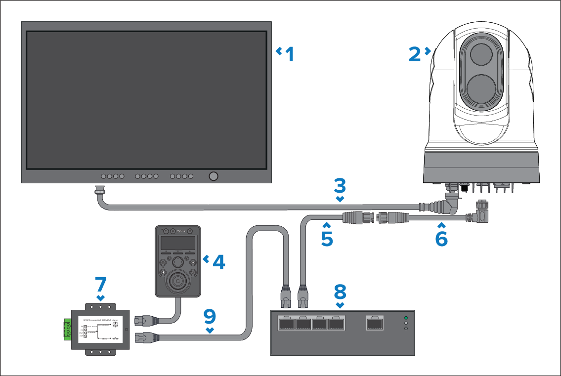
With the right combination of devices and connections, you can view and control the camera’s image from the most convenient locations on your vessel.
The following illustration shows a very typical installation scenario. For more system configuration examples, ranging from small to large systems, refer to: Network connections
For an overview of the camera’s video connection options, refer to: Video connections
It is recommended that an HD video isolation transformer is fitted to camera HD-SDI connections. Failure to install an inline HD video isolation transformer may invalidate the camera’s warranty. For more information, refer to:
If you are powering a JCU via the separately-available PoE Injector (2nd Generation; 5 Gbit) (A80811), do NOT connect the power input labelled “VIN1+” on the PoE Injector.
Power connections are not shown in this illustration. For power connection information, refer to the instructions which accompany each device.
Description |
|
|---|---|
1 |
Digital video (HD-SDI) monitor, available separately from third-party retailers |
2 |
M300-Series camera |
3 |
HD-SDI video cable (BNC connectors) (3 m / 9.8 ft.), supplied with camera |
4 |
Joystick control unit (JCU-4 currently illustrated), available separately |
5 |
RayNet (Ethernet) to RJ45 adapter cable (100 mm (3.9 in)), supplied with camera |
6 |
Right-angled RayNet (Ethernet) to RayNet (Ethernet) cable 3 m (9.8 ft.), supplied with camera |
7 |
PSE (Power Sourcing Equipment — e.g. a PoE Injector or PoE network switch) providing PoE (Power over Ethernet) to the JCU-2, available separately |
8 |
Ethernet network switch, available separately from third-party retailers |
9 |
RJ45 to RJ45 cable, available separately |