RVM1600 Installation Instructions
Let’s Go!
How to navigate this document
Legal notices
Important information
Safety warnings
Product installation and operation
High voltage
Switch off power supply
Transducer cables
Sonar operation
Product warnings
Maximum transducer cable length
Product grounding
Positive ground systems
Power supply voltage
Power supply protection
Do not cut transducer cables
Service and maintenance
Regulatory notices
Water ingress
Disclaimer
Declaration of Conformity
PSTI Compliance
Product disposal
Warranty policy and registration
IMO and SOLAS
Technical accuracy
Publication copyright
Document information
Applicable products
Product documentation
Document illustrations
Operation instructions
Multifunction display / chartplotter software version
Transducer installation instructions
Product and system overview
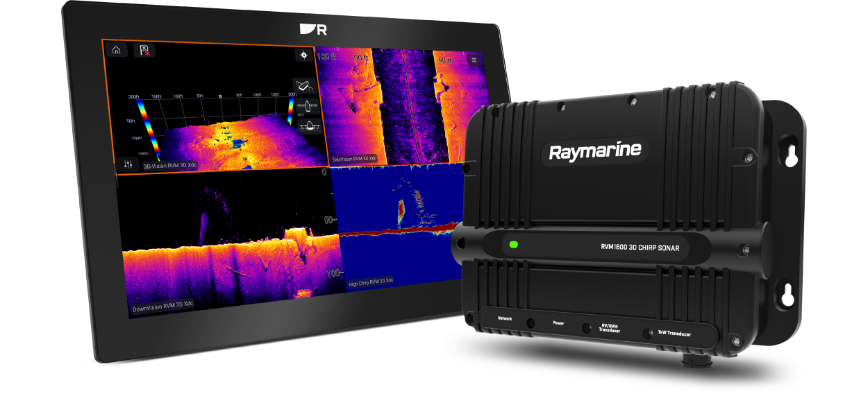
Product overview
Sonar channels
Sonar channel ranges
Sonar range
Traditional sonar range
Required additional components
Typical system
MFD / chartplotter software requirements
Compatible LightHouse 4 displays
Software updates
Installing software updates
Sonar technology overview
Sonar technology
Traditional sonar technology
CHIRP technology
Sonar overview
RealVision Max 3D overview
RealVision® 3D overview
DownVision® overview
SideVision® overview
CHIRP Sonar overview
Parts supplied
Parts supplied
Inline fuse requirement
Product dimensions
Product dimensions
Compatible transducers
Compatible transducers
Required cables — RealVision Max 3D transducers
RealVision Max 3D transducers
Required cables — RealVision 3D transducers
RealVision 3D transducers
Required cables — DownVision transducers
DownVision transducers
Required cables — CPT-S-Series conical beam transducers
CPT-S-Series conical beam transducers
Required cables — CHIRP transducers
CHIRP transducers
Required cables — Traditional transducers
Traditional transducers
Location requirements
Warnings and cautions
General location requirements
Ignition Protection
Cable routing requirements
EMC installation guidelines
Suppression ferrites
Connections to other equipment
Compass safe distance
Mounting
Tools required for installation
Fixing screw suitability
Mounting the unit
Cables and connections — General information
General cabling guidance
Cable types and length
Cable routing and bend radius
Strain relief
Circuit isolation
Cable shielding
Suppression ferrites
Connections to other equipment
Positive ground systems
Connecting cables
Connections overview
Example systems
Typical system
Expanded system
Network connections
Network connection
MFD / chartplotter network connection
Network cable extensions
Network connection to multiple MFDs / chartplotters
Power connections
Power connection
Inline fuse and thermal breaker ratings
Power distribution
Power cable extension (12 / 24 V systems)
Power cable drain wire connection
Transducer connections
Transducer connection overview
Transducer cables
Maximum transducer cable length
Do not cut transducer cables
RealVision® 3D / RealVision® Max 3D transducer connection
Split-pair RealVision® 3D / RealVision® Max 3D transducer connections
DownVision® transducer connections
CPT-S-Series conical beam transducer connections
CHIRP transducer connections
Traditional transducer connections
Simultaneous RealVision® 3D / RealVision® Max 3D transducer and traditional transducer connections
Transducer cable extension
Maximum transducer cable length
Operation
Operation instructions
Multifunction display / chartplotter software version
System checks and troubleshooting
Initial power-on test
Troubleshooting
LED Diagnostics
Sonar troubleshooting
Diagnostic product information
Resetting the sonar (LightHouse 4 / LightHouse 3)
Maintenance
Routine checks
High voltage
Unit cleaning instructions
Transducer cleaning
Re-applying anti-fouling paint
Technical support
Raymarine technical support and servicing
Diagnostic product information
Remote Support via AnyDesk™
Learning resources
Technical specification
Physical specification
Power specification
Environmental specification
Sonar specification
Sonar channels
Sonar range
Traditional sonar range
Conformance specification
Spares and accessories
Compatible transducers
Spares and accessories
Maximum transducer cable length
RayNet to RayNet cables and connectors
RayNet to RJ45, and RJ45 (SeaTalk HS) adapter cables
Interpreting the Sonar display
Factors influencing the sonar display
Interpreting the bottom
Interpreting objects on the sonar display
Thermoclines
Ethernet (IPv4) networking of Raymarine devices with third-party products