Typical system
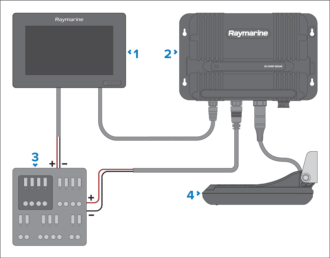
Example of a typical system, including the available connections and types of devices that can be connected.
System diagramTypical systemConnectionsConnectionsTypical system
This system configuration is shown as an example only and may differ from your planned installation.
Grounding connections and fuses are not shown in the illustration above, but MUST be implemented. Refer to the Power Connections section for more information on the correct implementation.
Compatible Raymarine MFD / chartplotter.
Sonar module.
Power supply for the RVM1600 (12 or 24 V dc), and MFD / chartplotter (refer to your display’s Installation Instructions for the specific voltage requirements for that device).
Transducer.
For information on how to connect your products, refer to the following sections:
For information on available cables and accessories, refer to the following section: Spares and accessories