Connecting mast cable to the gateway
The bare-ended wires on the supplied mast cable should be connected to the gateway after the mast cable has been routed to the gateway. The wire connections on the gateway are color-coded to match the mast cable wire colors.
Important
The wind transducer must be connected to the network using the supplied gateway and CANNOT be connected to an iTC-5 or an i60 instrument.
ConnectionsGateway Cable
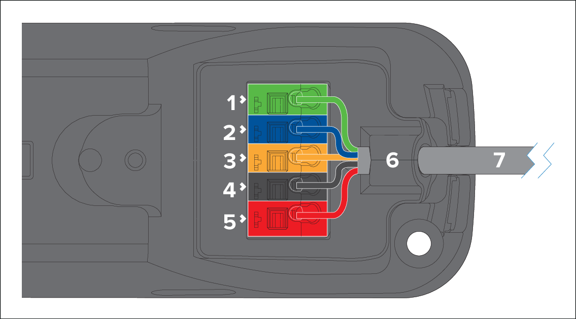
Terminal color |
Wire color |
Notes |
|
|---|---|---|---|
1 |
Green |
Green |
— |
2 |
Blue |
Blue |
— |
3 |
Yellow |
Yellow |
— |
4 |
Black |
Black |
— |
5 |
Red |
Red |
— |
6 |
— |
— |
Cable gland |
7 |
— |
— |
Mast cable |
- Position the gateway cover’s cable cutout groove above
the mast cable, and then push the cover down and forward. Before
engaging the gateway cover clips, ensure that the mast cable is positioned
at the top of the cover’s cutout groove.
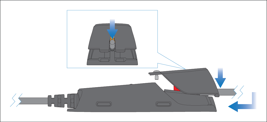
Important
To prevent water ingress, the gateway’s cover MUST be fitted in all installations.