Mounting system assemblies using the bracket
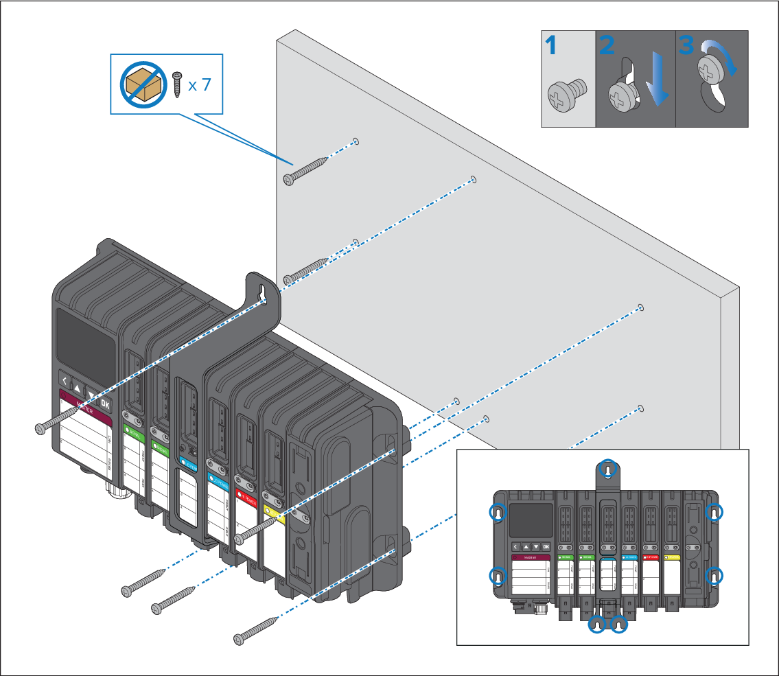
Follow the steps below to mount Master system assembly and Remote system assemblies that include 4 or more input / output modules.
Important
To help prevent water ingress, systems must be mounted vertically with the connectors facing down.
Use 7 x fixings, not supplied, appropriate for the intended mounting surface. The fixings should be appropriate width for the 5 mm (0.2 in) module mounting holes.
- Ensure that the mounting location requirements have been met.
- Hold the assembly in place at the intended location.
- Mark the location of the 2 holes on the Master module or Remote module (the holes on the left).
- Place the assembly to one side.
- Drill the 2 holes in the mounting surface.
- Screw in 2 x fixings approximately half way.
- Place the assembly over the 2 fixings and move down to the locked position.
- Use a spirit level to ensure the assembly is level and then mark the position of the 3 mounting holes in the mounting bracket and the 2 mounting holes in the Power supply module.
- Remove the assembly and drill the 5 holes in the mounting surface.
- Screw in the remaining 5 fixings approximately half way.
- Place the assembly over all fixings and move the assembly down into the locked position.
- Fully tighten all fixings.