Camlock system
Input and output modules and power supply modules include a camlock system that is used to lock the modules together. The camlock system consists of 3 camlocks on each module, one on the front and 2 on the rear. The modules are supplied with the camlocks in the unlocked position.
Camlock locking
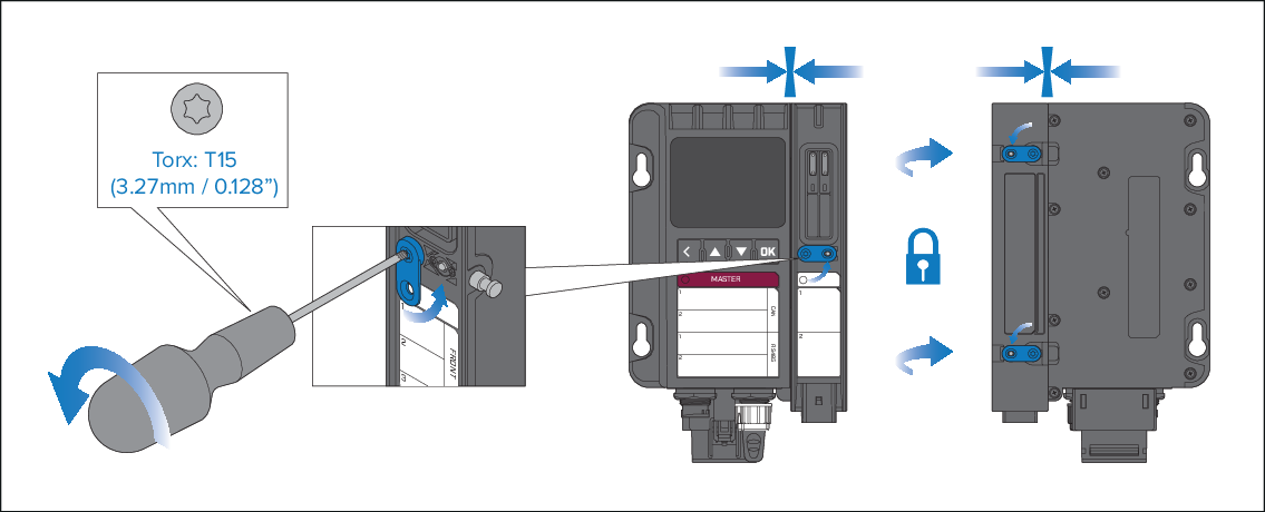
Figure 1. Locking the modules
Lock the modules in position one at a time. Hold the modules together, ensuring there is no gap between modules and use a T15 size torxs driver to turn the camlock counter-clockwise into the locked position.
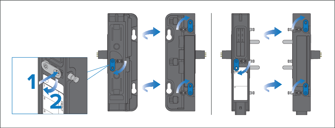
Figure 2. Unlocking the modules
Camlock unlocking
Push in the center pin and turn the camlock clockwise so that the camlock on the front of the module is pointing down and the camlocks on the rear of the module are pointing up. If the camlocks are stiff use a T15 size torxs driver to turn the camlocks.