Mounting the pedestal

Before mounting the unit, ensure that you have:

MountingRadarMountingPedestal

  • Selected a suitable location.

  • Identified the cable connections and route that the cables will take.

Important

Prepare suitable lifting equipment (e.g. steel cable or chain) to lift the pedestal into place in its final mounting position, prior to securing the mounting bolts. The lifting equipment must be of a suitable gauge and strength capable of bearing the pedestal's weight of 16 Kg (35.27 lbs) as a minimum, and also capable of passing through the 20 mm (0.79 in) eyebolt hole on the pedestal. Additionally, you must also carefully consider the impact force on the lifting equipment, in the event that the pedestal falls before it is secured to the mounting surface. Do NOT attach the antenna to the pedestal prior to lifting.

  1. Check the selected location. A clear, flat platform is required for mounting the pedestal unit.
    Important

    For more information refer to Location requirements

  2. Fix the supplied mounting template to the platform, using masking or self-adhesive tape.
    Important

    Ensure the mounting template is orientated correctly.
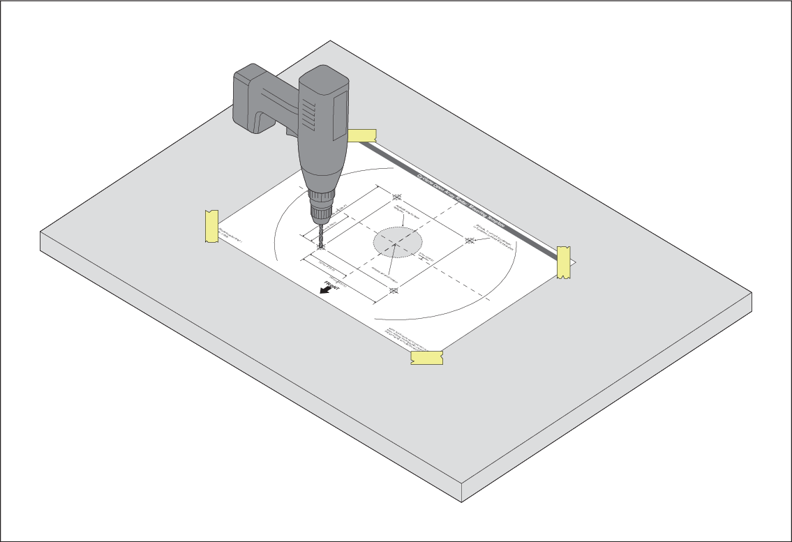
  3. Using a 3 mm (0.1 in) drill bit, drill the 4 holes as indicated on the mounting template. Check that the holes have been drilled in the correct position.
  4. Using an 11 mm (0.4 in) drill bit, drill through the 4 holes.
  5. If you plan to route your cables through the mounting surface, cut the cable hole out using a jigsaw.
  6. Remove the mounting template.
  7. The pedestal has a transit cover fitted over the open array. This cover must be left in place until the open array antenna is fitted to the pedestal.
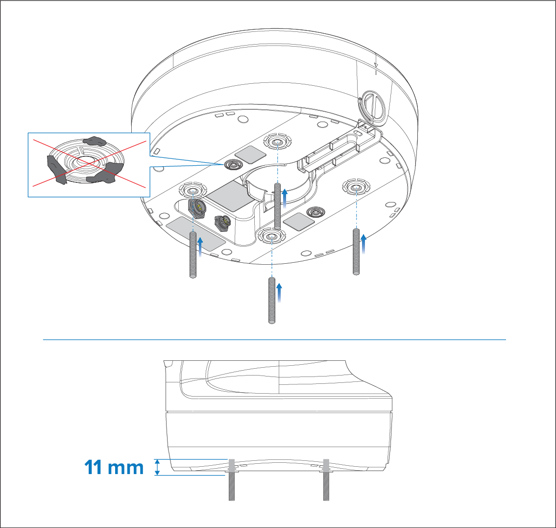
  8. Insert the studs no more than 11 mm (0.4) into the holes in the pedestal base, and hand-tighten. If the supplied studs are not long enough for the mounting surface thickness, use M10 stainless steel, grade A4-70 studding of a suitable length.
    Important

    Ensure the vents on the underside are not blocked.
  9. Pass a a suitable steel cable or chain through the 20 mm (0.8 in) eyebolt holes. Once secure, lift the pedestal and test it fits correctly in its final mounting position.
    Important

    Ensure the pedestal is orientated correctly.
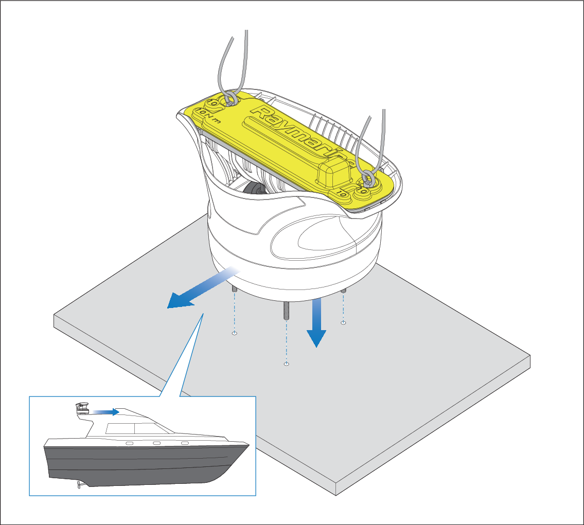
  10. Lift the pedestal up and connect the power and data cables to the connectors on the underside of the pedestal. Organize the cables in accordance with your planned cable routing and place the pedestal back into position. Ensure that you refer to the relevant cable routing instructions before proceeding to the next step:
    1. For rear exit cabling, refer to: Rear exit
    2. For through-surface cabling, refer to: Through-surface cabling
    Important

    Ensure that power is NOT supplied to the cables during the installation procedure.

  11. Grease the 4 metal studs using the supplied Denso paste.
  12. Referring to the following illustration, use the 4 nuts and associated washers to secure the pedestal to the platform.
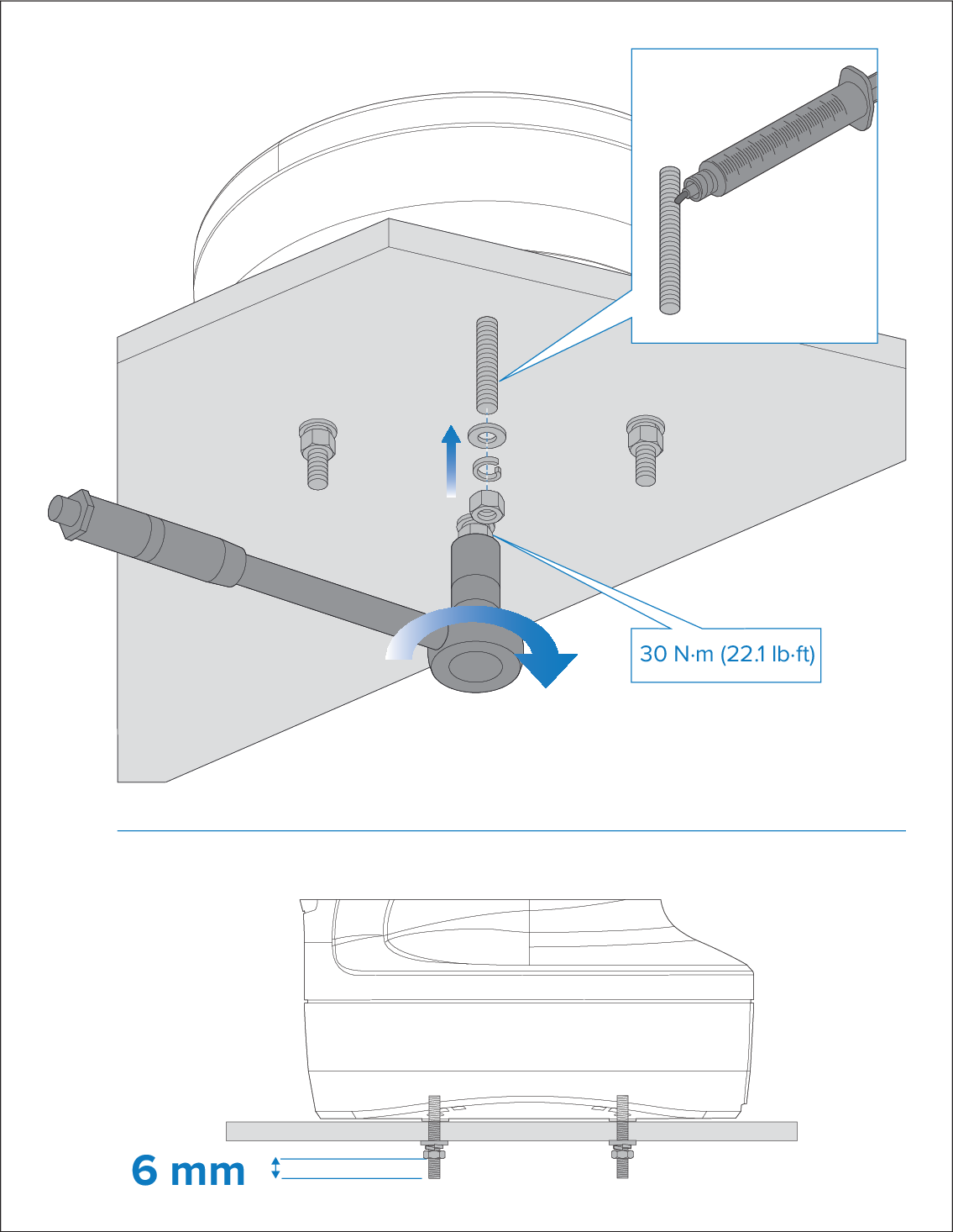
  13. Tighten each nut to a torque of 30 N·m (22.1 lb·ft). Ensure that all 4 sets of nuts and washers are used to secure the pedestal to the mounting platform.
  14. Cut-off any excess stud; there should be no more than 6 mm (0.2 in) of excess stud below the nut.