Cable routing — pole mount
Cable routing (pole mount)Pole mounting
Using separate power and data cables.
Using an existing combined power / data cable from an older Raymarine® Digital Radar scanner. In this scenario, the A80308 Y-adapter accessory is required (not supplied with the scanner).
The routing options described and illustrated in this section assume that a physical data connection is used between your Radar scanner and multifunction display (MFD) / chartplotter. However, if the Radar scanner is connected to your MFD via Wi-Fi, a physical RayNet connection is not required.
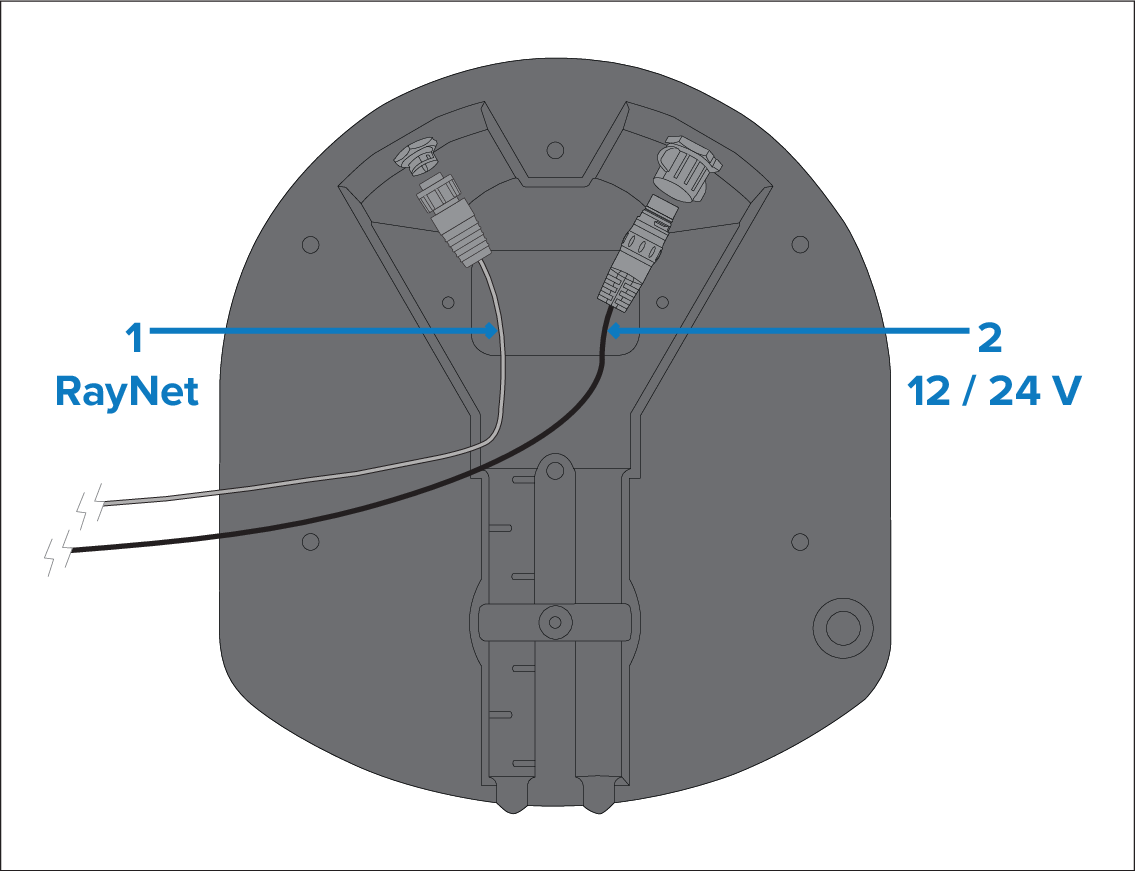
Figure 1. Scenario 1: Using separate power and data cables
RayNet data connection. (This connection is not required if connecting to the MFD via Wi-Fi.)
12 V / 24 V power connection, via the supplied power cable.
Not all Quantum™ radar variants are supplied with a RayNet cable. For more information, refer to: Document information
For information on suitable accessory RayNet cables, refer to: Spares and accessories
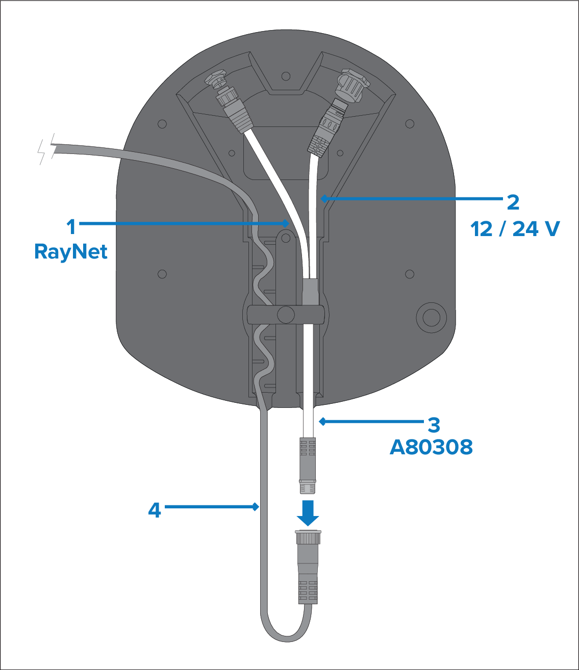
Figure 2. Scenario 2: Using an existing combined power / data cable from an older Raymarine Digital Radar
The Y-adapter cable is actually white. For clarity, it is shown in the above drawing in different colors.
RayNet data connection. (This connection is not required if connecting to the MFD via Wi-Fi.). This cable is part of the A80308 Y-adapter accessory cable.
12 V / 24 V power connection. This cable is part of the A80308 Y-adapter accessory cable.
A80308 Y-adapter accessory cable (not supplied with the scanner).
Existing combined Digital Radar power / data cable.