VCM100 power connections
VCM100 power and grounding requirements.
Power connectionsVCM100ConnectionsPowerVCM100
The VCM100 is intended for use on a vessel's DC power system, operating from 12 to 24 Volts DC.
The VCM100 must be connected to a battery isolator switch, or a DC distribution panel.
The battery isolator switch or DC distribution panel must be connected to the POWER IN terminals of the VCM100.
Do NOT connect additional power switches to the cable providing the power feed to the VCM100.
All power connections between the VCM100 and the power source must have appropriate fuse protection.
All power connections must be of high quality to minimize resistance and to remove the risk of accidental shorts.
The VCM100 SCREEN terminals must be connected to your vessel's RF ground system.
The distribution point should be fed from the vessel’s primary power source by 8 AWG (8.36 mm2) cable.
PowerSharing a breakerIdeally, all equipment should be wired to individual suitably-rated thermal breakers or fuses, with appropriate circuit protection. Where this is not possible and more than 1 item of equipment shares a breaker, use individual inline fuses for each power circuit to provide the necessary protection.
Do NOT connect the radar scanner or the VCM100 to a positively-grounded power system.
The following diagram illustrates the power connections of the VCM100:
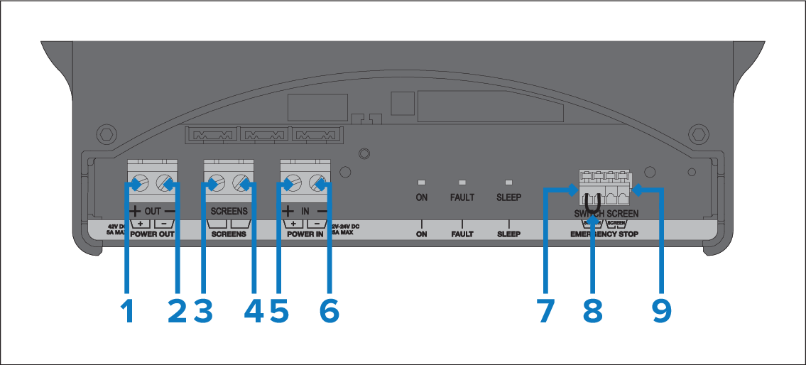
POWER OUT (Positive) — connect to the RED wire of the radar scanner power cable.
POWER OUT (Negative) — connect to the BLACK wire of the radar scanner power cable.
SCREEN — connect to the bare screen (drain) strands of the radar scanner power cable.
SCREEN — connect to your vessel's RF ground system.
POWER IN (Positive) — connect to the positive terminal of the vessel’s power supply (ideally a battery isolator switch or DC distribution panel).
POWER IN (Negative) — connect to the negative terminal of the vessel’s power supply (ideally a battery isolator switch or DC distribution panel).
EMERGENCY STOP (Switch) — if you have an optional VCM100 emergency stop button, remove the wire bridging link from the VCM100 EMERGENCY STOP terminals, and connect the emergency stop button SWITCH wire to the VCM100 EMERGENCY STOP SWITCH terminal.
EMERGENCY STOP wire bridging link — only remove if fitting the optional emergency stop button.
EMERGENCY STOP (Screen) — if you have an optional VCM100 emergency stop button, remove the wire bridging link from the VCM100 EMERGENCY STOP terminals, and connect the emergency stop button SCREEN (drain) wire to the VCM100 EMERGENCY STOP SCREEN terminal.
When planning and wiring, take into consideration other products in your system, some of which (e.g. sonar modules) may place large power demand peaks on the vessel’s electrical system, which may impact the voltage available to other products during the peaks.
The information provided is for guidance only, to help protect your product. It covers common vessel power arrangements, but does NOT cover every scenario. If you are unsure how to provide the correct level of protection, please consult an authorized dealer or a suitably qualified professional marine electrician.
More information
InstallationBest practiceIt is recommended that best practice is observed in all vessel electrical installations, as detailed in the following standards:
BMEA Code of Practice for Electrical and Electronic Installations in Boats
NMEA 0400 Installation Standard
ISO 13297: Small craft — Electrical systems — Alternating and direct current installations
ISO 10133: Small craft — Electrical systems — Extra-low-voltage d.c. installations
ABYC E-11 AC & DC Electrical Systems on Boats
ABYC A-31 Battery chargers and Inverters
ABYC TE-4 Lightning Protection