Cable routing options
Cable routing
The available routing options allow for the cable to exit the Radar in 3 different positions. The option you choose will depend on the Radar mounting location:
Rear-horizontal cable exit — if the Radar is mounted on an extended flat surface, and the cable cannot be routed through the surface.
Rear-vertical cable exit — if the Radar is mounted on a truncated flat surface that does not extend far beyond the rear of the flat Radar base, and the cable cannot be routed through the surface.
Base cable exit — if the Radar is mounted on a flat surface, and the cable can be routed through the surface.
The following examples show how to route the cable in each scenario.
The Illustrations below show the Radar with the rear cover removed. For more information on how to remove the rear cover, refer to: Making the connection to the Radar
Rear-horizontal cable exit (Radar mounted to extended flat surface):
Cable routingRear-horizontal cable exit
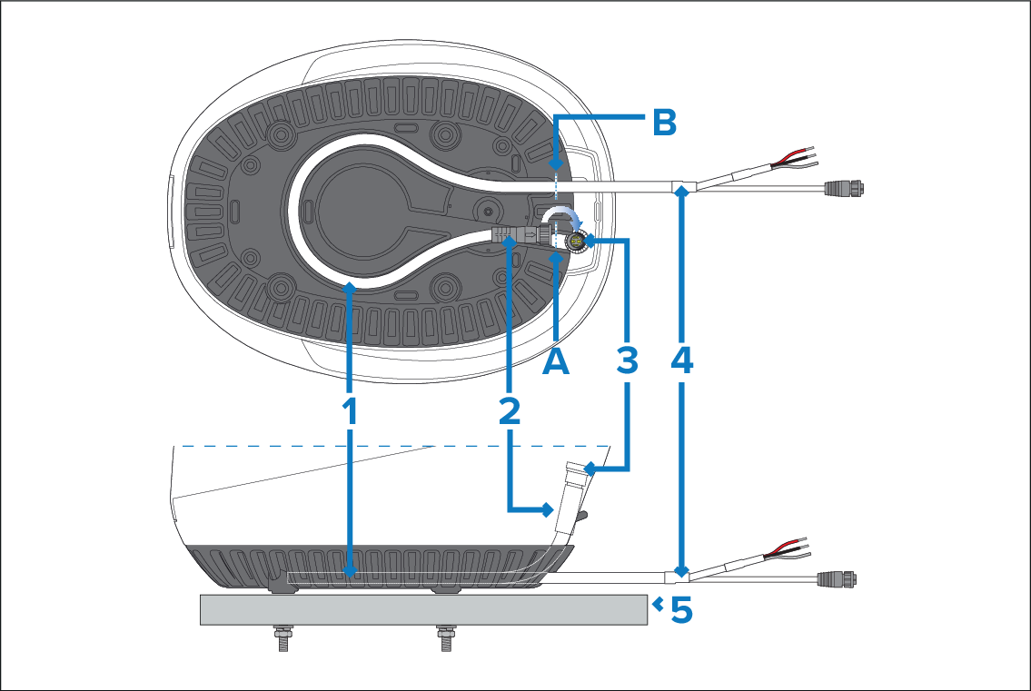
When laying the cable between the power supply / network connections and the cable’s rear exit point from the Radar, ensure that approximately 650 mm (26 in) of cable is available for routing within the Radar base to the power-and-data connector. This length of cable is shown between the dashed lines (between A and B) in the illustration above.
Cable routed through channel in Radar base.
Cable plug.
Power-and-data connector.
Combined power-and-data cable.
Mounting surface.
Rear-vertical cable exit (Radar mounted to truncated flat surface):
Cable routingRear-vertical cable exit
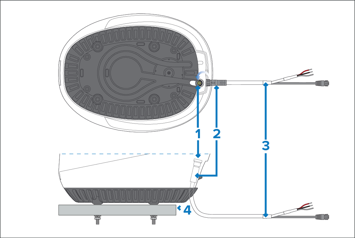
- Power-and-data connector.
Cable plug.
Combined power-and-data cable.
Mounting surface.
Base cable exit (Radar mounted to flat surface):
Cable routingBase cable exit
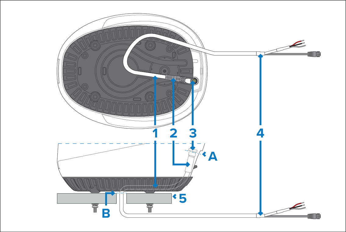
When laying the cable between the power supply / network connections and the cable’s bottom exit point from the Radar, ensure that approximately 255 mm (10 in) of cable is available for routing within the Radar base to the power-and-data connector. This length of cable is shown between the dashed lines (between A and B) in the illustration above.
Cable routed through channel in Radar base.
Cable plug.
Power-and-data connector.
Combined power-and-data cable.
Mounting surface.