Expanded system example
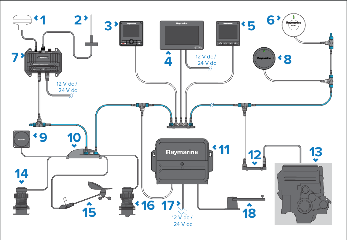
The following example provides an overview of an expanded system, including the available connections and the types of analog transducers that can be connected to your iTC-5.
System diagramConnections
This system is shown as an example only, and may differ from your planned installation.
Depending on engine type, it may be possible to connect the engine system directly to the SeaTalk NG backbone using a SeaTalk NG to DeviceNet adaptor cable. However, the data available will be restricted to supported, standard NMEA 2000 data only.
Description |
|
|---|---|
1 |
AIS dedicated GNSS (GPS) receiver. |
2 |
VHF antenna. |
3 |
SeaTalk NG pilot controller (e.g.: p70Rs). |
4 |
MFD / chartplotter (e.g.: Axiom+). |
5 |
i70s instrument display. |
6 |
GNSS (GPS) (e.g.: RS150). |
7 |
AIS receiver / transceiver (e.g.: AIS700). |
8 |
Evolution autopilot (e.g.: EV-1). |
9 |
Fluxgate compass (Analog). |
10 |
iTC-5. |
11 |
Autopilot control unit (e.g.: ACU-400). |
12 |
ECI-100. |
13 |
Vessel / Engine systems. |
14 |
Depth transducer (Analog). |
15 |
Wind transducer (Analog). |
16 |
Speed / Temperature transducer (Analog). |
17 |
12 V dc / 24 V dc power supply (supplying 12 V dc to the SeaTalk NG backbone via the ACU-400). |
18 |
Rudder reference transducer (Analog). |
For information on how to connect your products, refer to the following sections:
For information on the available cables and accessories, refer to the following section: Spares and accessories