Toggle output connection
The connection diagram is provided as an example of how to connect a Toggle output channel (items 1 and 2) via a relay (5) to control a device. The other components in the diagram may not reflect your installation and sound electrical judgement should always be used when attempting to connect the router’s output channels.
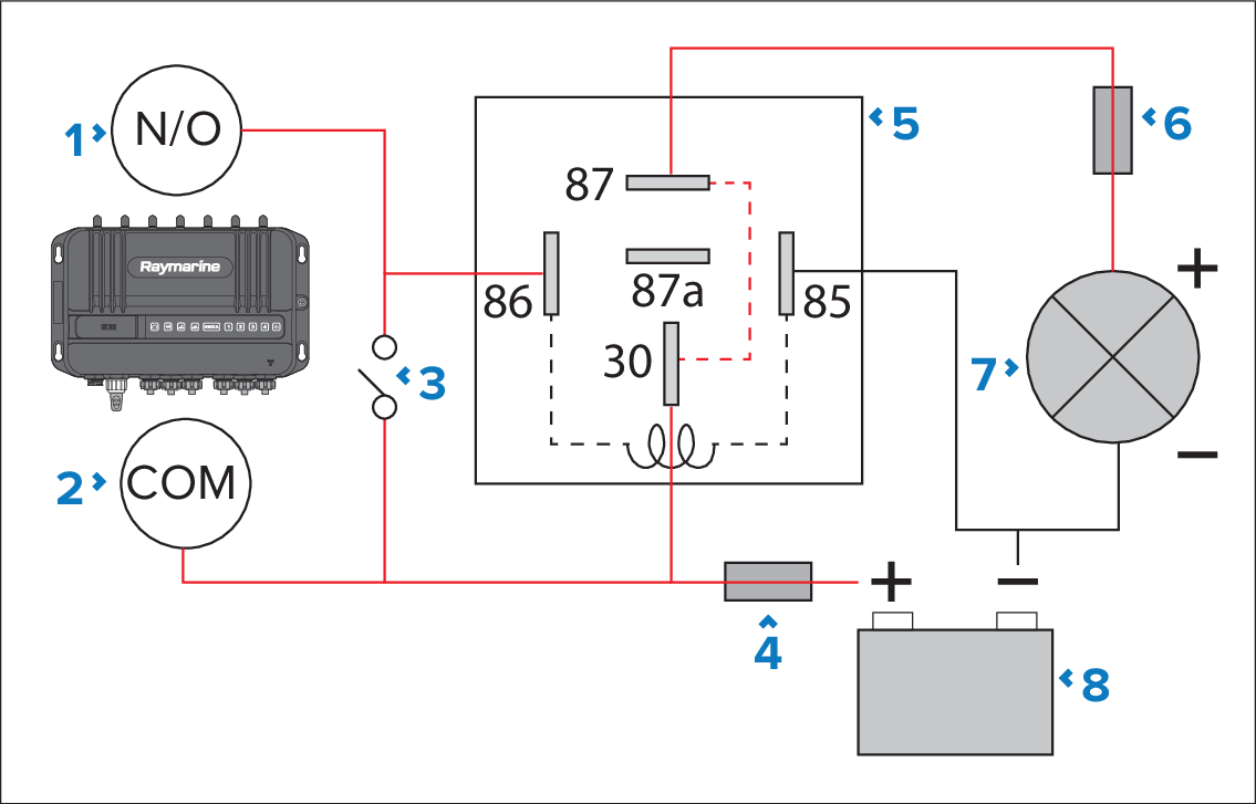
Figure 1. Example automotive 4 or 5 pin relay (type B) connection diagram
Router output channel Normally Open terminal (e.g.: Output 1 White wire).
Router output channel Common terminal (e.g.: Output 1 Black wire).
Parallel switch.
Suitably rated power supply fuse.
Automotive 5 pin relay
30 — High power feed.
86 — Relay coil feed (Trigger wire).
85 — Relay coil ground.
87 — High power output (normally open contact).
87a — High power output (normally closed contact).
Suitably rated device fuse.
Device (e.g.: lighting).
Power supply.