Pulse output connection
The connection diagram below is provided as an example of how to connect a Pulse output channel (items 1 and 2) to control a device that requires either: a pulse to switch on and a pulse to switch off, or a momentary device that only requires power for less than 30 seconds. Please note, the other components shown in the diagram may not reflect your specific installation, and sound electrical judgement should always be used when attempting to connect the router’s output channels.
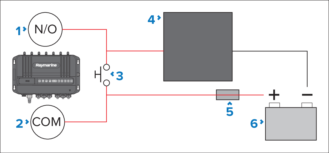
Figure 1. Example pulse/momentary output connection diagram
Router output channel Normally Open (N/O) terminal (e.g.: Output 1, White wire).
Router output channel Common (COM) terminal (e.g.: Output 1, Black wire).
Push or momentary switch.
Device.
Suitably-rated fuse.
Power supply.