Input channel connections
The input channels can be configured as follows:
Analog — voltage monitoring from 0 V dc to supply voltage.
Digital — switch state detection when connected between channel and supply voltage. Switches can be normally open or normally closed.
The input channel configuration details refer to: Configuring input channels
The input channel cannot detect switch state on switches that are switched to negative supply.
All connections to positive voltage supply should be fused appropriately.
When configured for digital switch detection, an input channel can be used to wake the router from low power mode. Refer to the Power management page of the router’s web interface for settings.
The input channels are protected up to 32 V dc (in case of inadvertent connection) and are opto isolated when driven from another device or supply.
The input channel will automatically switch between low voltage (0 V dc to 8 V dc) and High voltage (8 V dc to supply voltage). The two thresholds are for the application of hysteresis.
Example connections
ConnectionsDigital input
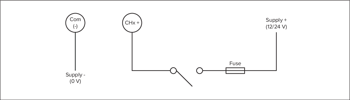
Figure 1. Example — Switch detection (Digital)
ConnectionsDigital inputVoltage monitor
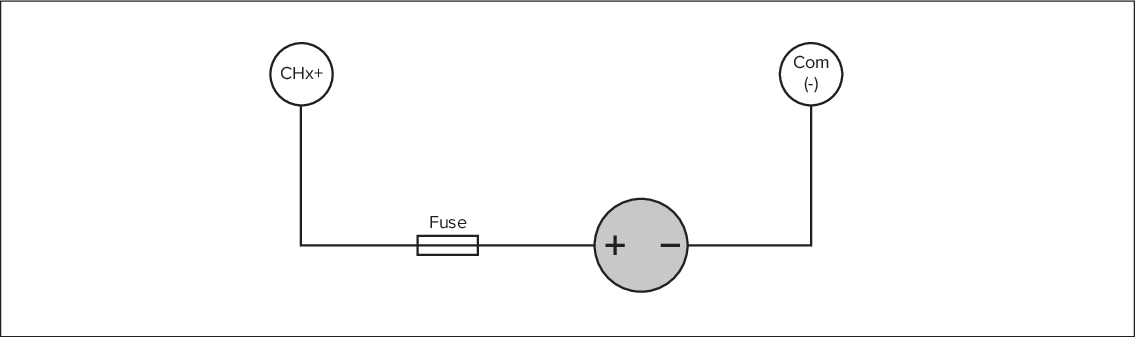
Figure 2. Example — Voltage monitor (Analog)