Wiring the connectors

Follow the instructions below to wire the connector terminals.

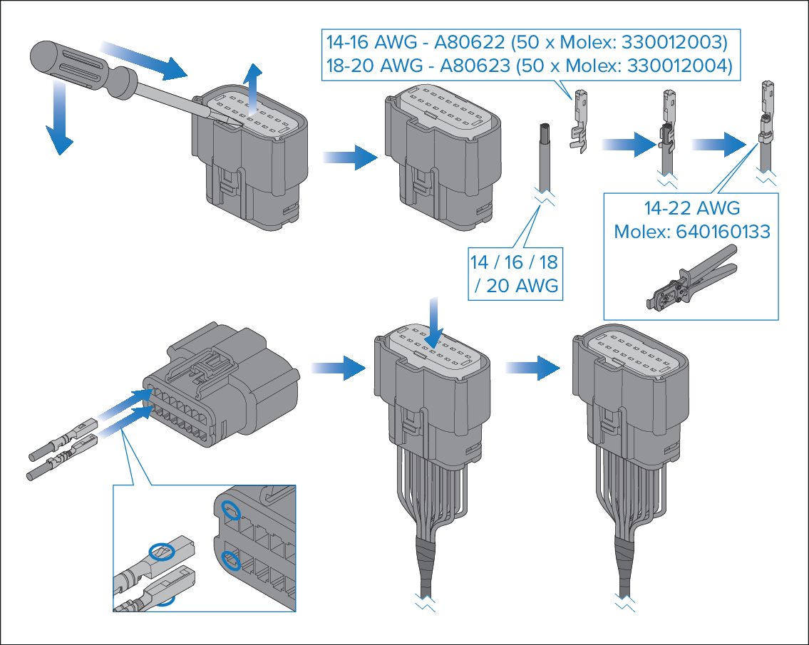
When wiring the connector the appropriate size female receptacle crimps are required:

  • For 14 and 16 AWG wire Molex® crimps 330012003 are required.

  • For 18 and 20 AWG wire Molex® crimps 330012004 are required.

Important
  • To protect against water ingress fit seal plugs (Molex® part number: 343450001) to any unused terminals.

  • Ensure seal plugs are fitted and trimmed before fitting wiring the connector terminals.

MolexCrimpsWiring
  1. Disconnect the connector from the module.
  2. If, required, insert a small flat blade screwdriver into the pry point and using the connector housing as a pivot point, pry out the connector insert, known as the TPA (Terminal Position Assurance), until it reaches the pre-lock position.
  3. Ensure seal plugs have been fitted to any terminals that will not be wired. For instructions on inserting seal plugs see: Inserting seal plugs
  4. Prepare each wire by stripping the insulation by 4.70 mm (0.19 in) to 5.60 mm (0.22 in).
  5. Place the wire in a female receptacle crimp so that the exposed copper is level with the end of the conductor crimp and the insulation protrudes slightly from the end of the insulation crimp.

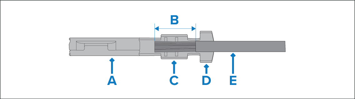
    A — Female crimp connector

    B — Exposed copper – 4.70 mm (0.19 in) to 5.60 mm (0.22 in).

    C — conductor crimp

    D — Insulator crimp

    E — Wire insulation

  6. Using an appropriate crimping tool, crimp the connector.

    (Molex® 14–22 AWG hand crimp tool (Molex® part number: 640160133)

  7. Ensuring correct orientation, insert the wire crimp connector into the relevant connector terminal.
  8. Pull back on the wire to ensure it has locked into place.
  9. Repeat steps 4 to 8 for each wire that is required.
  10. Once all wires and any seal plugs have been inserted, push down on the connector insert (known as the TPA (Terminal Position Assurance) until it clicks and reaches the locked position.
  11. If required, tape wires together approximately 30 mm (1.18 in) below the bottom of the connector using suitable insulation tape, leave