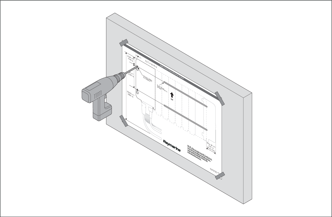
Mounting using the mounting template
A supplied mounting template can aid installation in confined or difficult to reach places.
Important
To help prevent water ingress, systems must be mounted vertically with the connectors facing down.
Use fixings (not supplied) appropriate for the intended mounting surface. The fixings should be appropriate width for the 5 mm (0.2 in) module mounting holes.
Either 4 or 7 fixings are required. 4 for assemblies with less than 4 input / output modules and 7 fixings for assemblies with 4 or more input / output modules (4 for the assembly mounting holes and 3 for the mounting bracket).
- Ensure that the mounting location requirements have been met; refer to: Location requirements
- Place the mounting template on a flat surface and ensure it is not creased or folded.
- Place the assembly on the mounting template and line up the mounting holes in the Master module or Remote module with the relevant mounting holes on the template.
- Ensuring the assembly is level on the template, mark the location of the 2 mounting holes in the Power supply module on the mounting template.
- Secure the mounting template in the required location using adhesive tape.
- Drill 4 or 7 holes at the marked locations.
- Screw in 4 or 7 fixings approximately half way.
- Place the assembly over all the fixings and move the assembly down into the locked position.
- Fully tighten the fixings.