Mounting the camera ball-down
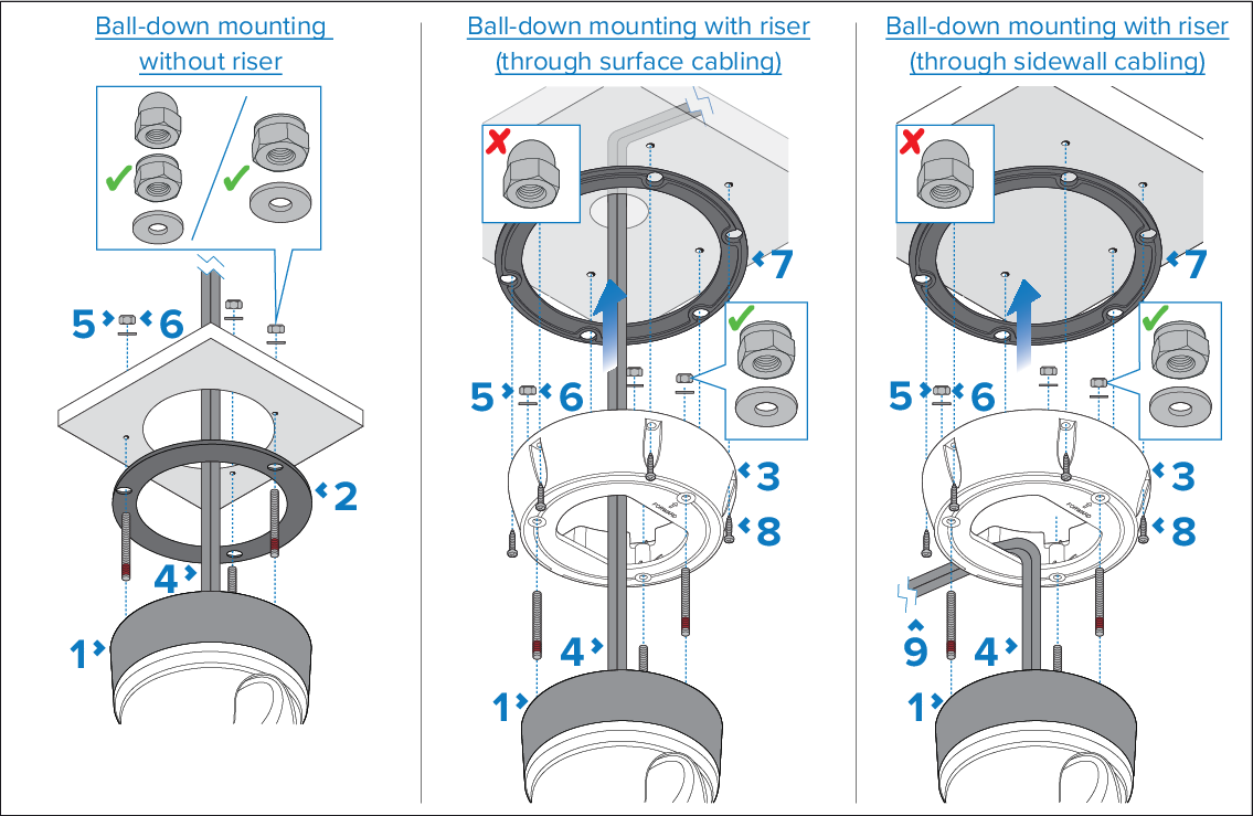
Use these instructions to mount the camera unit in the “Ball-down” (upside down) mounting position.

Note

When installing the camera in the “Ball-down” (upside down) mounting position, the camera should be fitted to a weather-tight, flat and stiff mounting surface, with no open air exposure. If a cutout is required in the mounting surface to accommodate the cables, ensure that the underside of the camera and any connections made are protected from potential water ingress, fouling and sun damage. If this is not possible, consider mounting the camera using the supplied riser, and routing the cables through the riser sidewall. An optional 20 mm (0.79 in.) wide, removable hatched area is provided on the riser for this purpose. For more information, refer to: Routing cables through the riser's sidewall

Note
  • The 2 supplied flat nuts must only be used to assist in winding the studs into the camera’s base. For more information, refer to: Inserting the studs into the camera base

  • Ensure that the supplied threaded studs have been installed in the correct orientation, as shown in the following section: Inserting the studs into the camera base

  • If required, you can fit the supplied dome nuts to the studs in order to cover exposed ends. Do NOT use dome nuts with a riser.

  1. Use the supplied mounting template to drill the holes for the camera base (or riser, if used), and the cables.
  2. Place the camera seal on the bottom of the camera, carefully aligning the seal holes with the threaded studs.
    Important

    If you are mounting the camera in the ball-down (upside down) position, do NOT fit the camera seal between the camera and the riser.

  3. Optionally, (temporarily) secure the riser to the camera with a few hand turns of the nyloc nuts on the studs, to prevent the riser from falling while you connect the cables. Check that the camera seal remains firmly in place.
    Note

    Observe the camera forward marking on the top surface of the riser. You must ensure that the riser is mounted so that the camera is orientated properly, relative to the vessel's bow.

  4. Connect the cables to the camera. If using the riser, either:
    • Loop the cables round within the riser base so that they can be threaded through the bottom of the riser and into the cable routing hole drilled in the mounting surface; or:

    • Loop the cables round within the riser base so that they can be threaded through the removed riser sidewall hatched area. For more information on how to remove the sidewall hatch, refer to: Routing cables through the riser's sidewall

  5. Secure the camera assembly to the mounting surface (or riser, if used), using the supplied flat washers and nyloc nuts. Pay careful attention to the correct arrangement of the fixings, as shown in the image above.
    Important

    If you are replacing an existing camera installation or have purchased an older riser, do NOT use the existing spring washers supplied with the camera or riser.

  6. Tighten the nyloc nuts to a torque of 5.0 to 6.0 N·m (3.7 to 4.4 lbf·ft).
  7. Fit the supplied riser base-seal to the riser.
  8. Secure the riser to the mounting surface using screws suitable for the mounting surface material and thickness. (Fixings not supplied).
  9. If the riser sidewall hatched area has been removed, apply an appropriate marine-grade sealant to the opening after cables have been routed, so that the area is weather-tight with no open air exposure.
  10. Add a regular check to ensure that weight bearing mountings, risers and fixings remain secure and without signs of wear or damage to your routine vessel maintenance schedule.