System overview
The following example provides an overview of a typical system, including the available connections and the types of devices that can be connected to your network switch.
Example: typical system
System diagramConnectionsTypical systemThe following system is shown as an example only, and may differ from your planned installation.
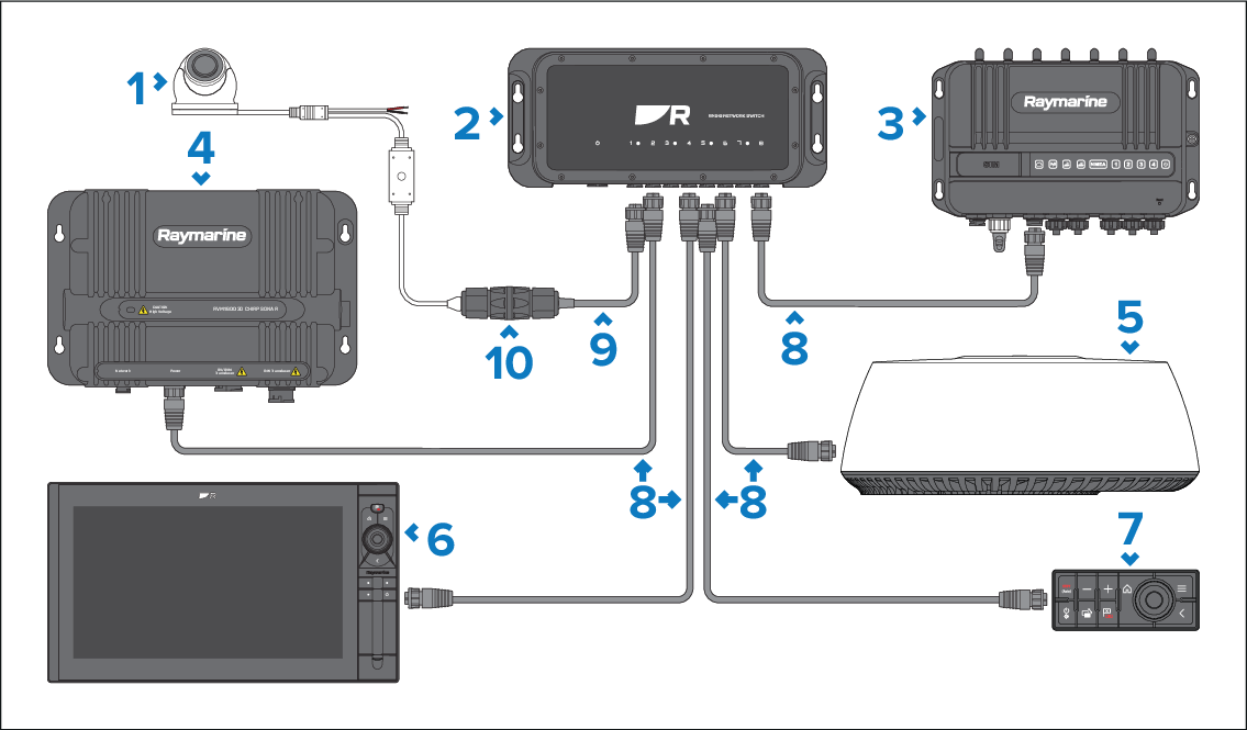
Description |
|
|---|---|
1 |
IP camera, powered via PoE. |
2 |
RNS-8 network switch. |
3 |
Marine router (YachtSense Link shown). |
4 |
Sonar module (RVM1600 shown). |
5 |
Radar scanner (Quantum 2 shown). |
6 |
Multifunction display / chartplotter (Axiom 2 Pro shown). |
7 |
Remote keypad, powered via PoE (RMK-10 shown). |
8 |
RayNet (female) to RayNet (female) network cable (not supplied). |
9 |
RayNet (female) to RJ45 (male) network cable (not supplied). |
10 |
RJ45 to RJ45 waterproof coupler. (part number 4115028, not supplied). |
For information on how to connect your products, refer to the following sections:
For information on the available cables and accessories, refer to the following section: Spares and accessories