Preparing the mounting surface — flush mounting
When the display is flush mounted, the glass/bezel will be flush with the mounting surface. Flush mounting requires the same cutout hole as surface mounting, plus an additional rebate around the edge of the cutout to recess the display fully in the mounting surface.
The following procedure is for preparing the mounting surface for flush mount installations. For surface mounting details refer to: Preparing the mounting surface — surface mounting
Before preparing the mounting surface, ensure that:
your selected location meets the location requirements. For details refer to: Location requirements
you have identified cable connections and the route that the cables will take.
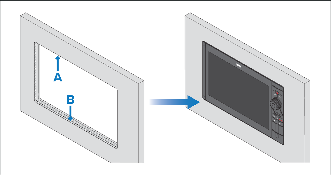
A — Cutout (when flush mounting, the cutout will be the same dimensions as the cutout used for surface mounting).
B — Flush mounting requires an extra rebate to recess the display fully in the mounting surface.
When flush mounting, the fixings go through holes drilled in the rebated, and therefore thinnest, part of the mounting surface. Before preparing the mounting surface, ensure that sufficient surface thickness will remain (once rebated) to take the weight of the display. The final rebated area must be at least as thick as the display’s bezel (15.00 mm (0.59 in)), in order to ensure that the display sits entirely flush with the mounting surface. Due to these requirements, not all mounting surface types and materials are suitable for flush mounting the display. It is the installer’s responsibility to ensure that the mounting surface is suitable for flush mounting. If the mounting surface is not suitable, the display must be surface or trunnion mounted instead.