Power distribution — SeaTalk NG
ConnectionsPower connectionsPower distributionSeaTalk NG
Only use approved SeaTalk NG power cables. Do NOT use a power cable designed for, or supplied with, a different product.
See below for more information on implementation for some common power distribution scenarios.
When planning and wiring, take into consideration other products in your system, some of which (e.g. sonar modules) may place large power demand peaks on the vessel’s electrical system, which may impact the voltage available to other products during the peaks.
The information provided below is for guidance only, to help protect your product. It covers common vessel power arrangements, but does NOT cover every scenario. If you are unsure how to provide the correct level of protection, please consult an authorized Raymarine dealer or a suitably qualified professional marine electrician.
Implementation — connection to distribution panel (recommended)
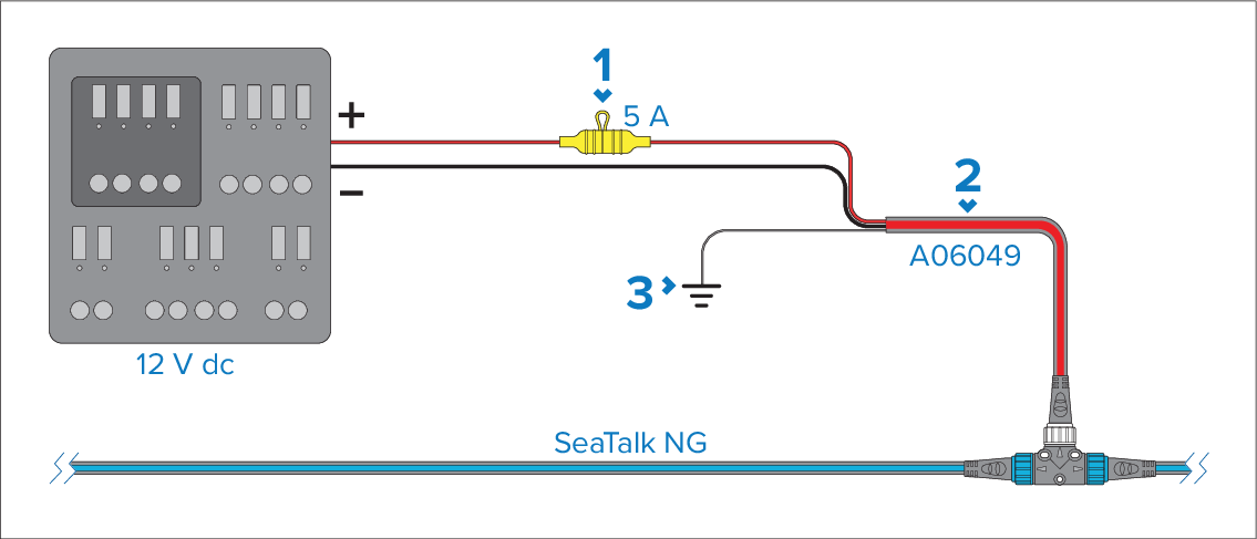
Waterproof fuse holder with 5 A inline fuse must be fitted (not supplied).
SeaTalk NG power cable.
RF Ground connection point for drain wire.
ConnectionsDistribution panelPowerDistribution panelIdeally, the SeaTalk NG power cable should be connected to a suitable breaker or switch on the vessel's Distribution panel connection distribution panel or factory-fitted power distribution point. It is recommended that a 5 A inline fuse is fitted to the red (positive) wire of the SeaTalk NG power cable.
The distribution point should be fed from the vessel’s primary power source by 8 AWG (8.36 mm2) cable.
PowerSharing a breakerIdeally, all equipment should be wired to individual suitably-rated thermal breakers or fuses, with appropriate circuit protection. Where this is not possible and more than one item of equipment shares a breaker, use individual in-line fuses for each power circuit to provide the necessary protection.
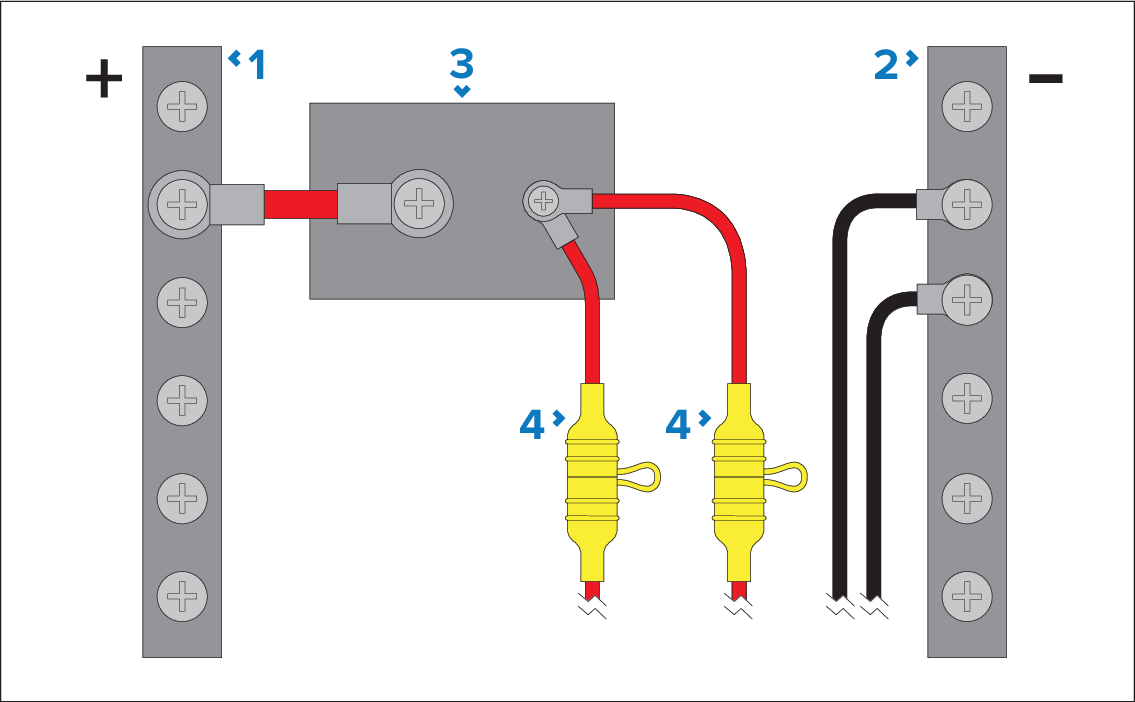
Positive (+) bar
Negative (-) bar
Circuit breaker
Waterproof fuse holder with 5 A inline fuse must be fitted (not supplied).
Observe the recommended fuse / breaker ratings provided in the product’s documentation, however be aware that the suitable fuse / breaker rating is dependent on the number of devices being connected.
Implementation — direct connection to battery
ConnectionsBatteryPowerBattery connectionWhere connection to a power distribution panel is not possible, the power cable may be connected to the vessel's battery.
You MUST fit a 5 A inline fuse between the red wire and the battery’s positive terminal.
If you need to extend the length of the power cable, ensure you use suitably rated cable and that sufficient power (12 V dc) is available at the SeaTalk NG backbone’s power connection.
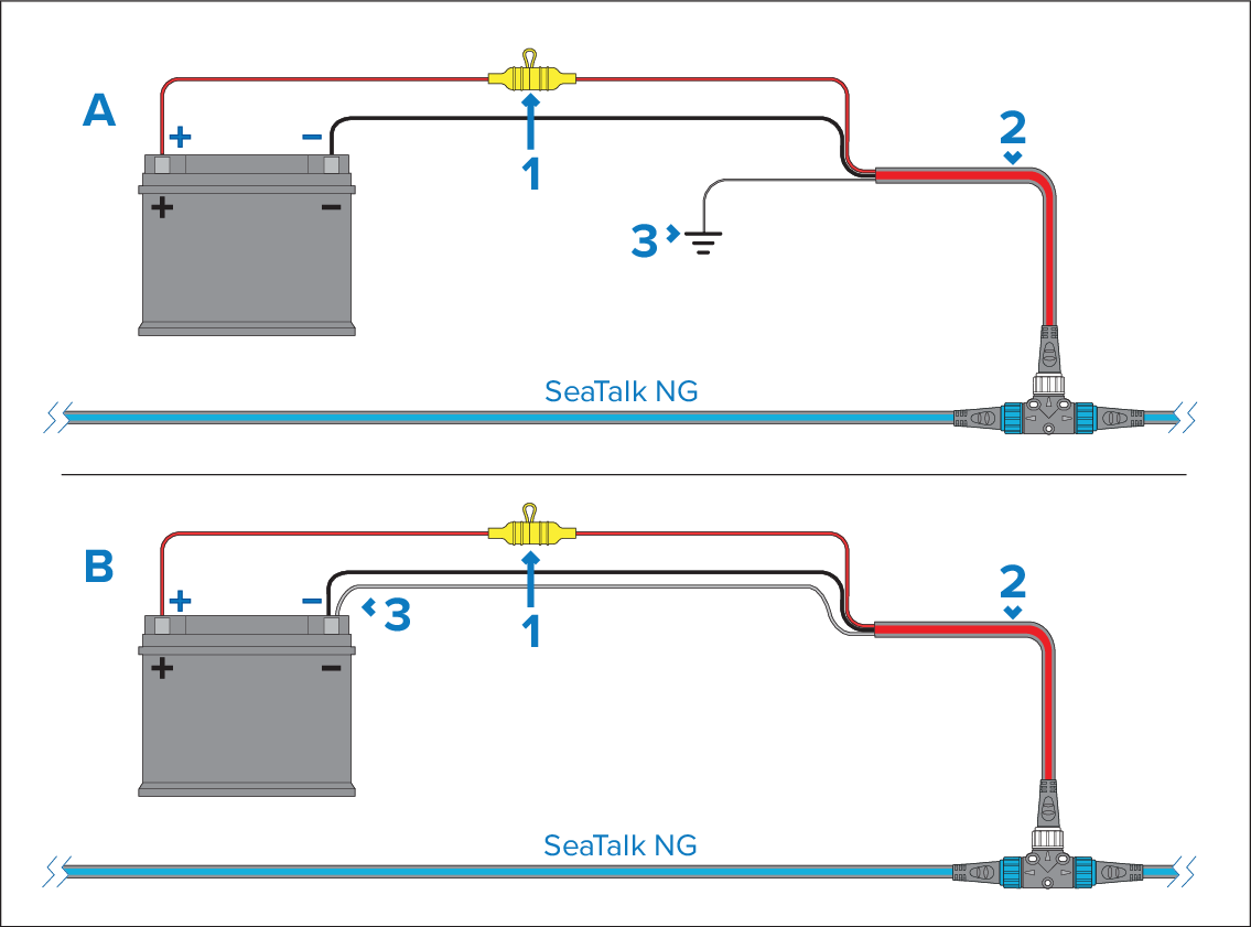
Waterproof fuse holder with 5 A inline fuse must be fitted (not supplied).
SeaTalk NG power cable.
Connection point for drain wire.
Battery connection scenario A:
Suitable for a vessel with a common RF ground point. In this scenario, the power cable’s drain wire should be connected to the vessel’s common RF ground point.
Battery connection scenario B:
Suitable for a vessel without a common RF ground point. In this scenario the power cable’s drain wire should be connected directly to the battery’s negative terminal.
SeaTalk NG Power cable extension
Power cable extensionIf you need to extend the length of the SeaTalk NG power cable, ensure you use suitably-rated cable, and that sufficient power is available at the SeaTalk NG backbone’s power connection point:
For power cable extensions, a minimum wire gauge of 16 AWG (1.31 mm2) is recommended. For cable runs longer than 15 m (49.2 ft), you may need to consider a thicker wire gauge (e.g. 14 AWG (2.08 mm2), or 12 AWG (3.31 mm2).
To ensure power cables (including any extension) are of a sufficient gauge, ensure that there is a continuous minimum voltage of 10.8 V dc at the end of the cable where it enters the product’s power connector, even with a fully flat battery at 11 V dc. (Do not assume that a flat battery is at 0 V dc. Due to the discharge profile and internal chemistry of batteries, the current drops much faster than the voltage. A “fully flat” battery still shows a positive voltage, even if it doesn’t have enough current to power your device.)
Be aware that some products in your system (such as sonar modules) can create voltage peaks at certain times, which may impact the voltage available to other products during the peaks.
More information
It is recommended that best practice is observed in all vessel electrical installations, as detailed in the following standards:
BMEA Code of Practice for Electrical and Electronic Installations in Boats
NMEA 0400 Installation Standard
ISO 13297: Small craft — Electrical systems — Alternating and direct current installations
ISO 10133: Small craft — Electrical systems — Extra-low-voltage d.c. installations
ABYC E-11 AC & DC Electrical Systems on Boats
ABYC A-31 Battery chargers and Inverters
ABYC TE-4 Lightning Protection