Grounding — optional grounding point
The ground point should ONLY be connected when touchscreen interference is observed.
Dedicated groundingConnectionsOptional grounding
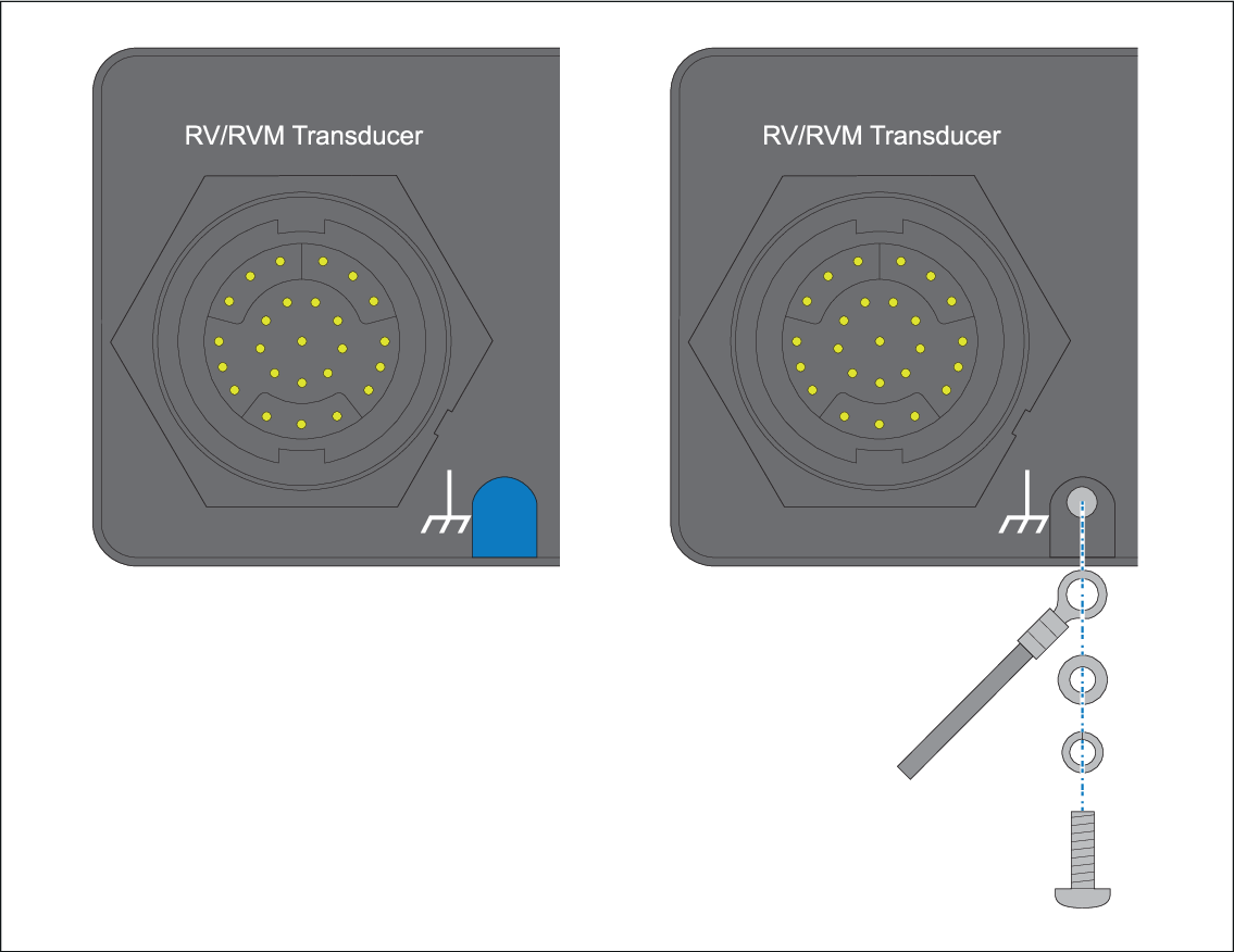
Use a small flat blade screwdriver to remove the grounding screw hole cover.
Connect one end of the ground wire (not supplied) to your display using the supplied crimp, washer and screw.
Connect the other end of the ground wire to either the vessel's RF ground point, or on vessels without an RF ground system, the negative battery terminal.
The dc power system should be either:
Negative grounded, with the negative battery terminal connected to the vessel's ground; or
Floating, with neither battery terminal connected to the vessel's ground.
If several items require grounding, they may first be connected to a single local point (e.g. within a switch panel), with this point connected via a single, appropriately-rated conductor, to the vessel’s common RF ground point.
Implementation
The preferred minimum requirement for the path to ground is via a flat tinned copper braid, with a 30 A rating (1/4 inch) or greater. If this is not possible, an equivalent stranded wire conductor may be used, rated as follows:
for runs of <1 m (3 ft), use 6 mm2 (#10 AWG) or greater.
for runs of >1 m (3 ft), use 8 mm2 (#8 AWG) or greater.
In any grounding system, always keep the length of connecting braid or wires as short as possible.
References
ISO10133/13297
BMEA code of practice
NMEA 0400