Pedestal power connections
Power connectionConnectionsPowerVCM100Power connection
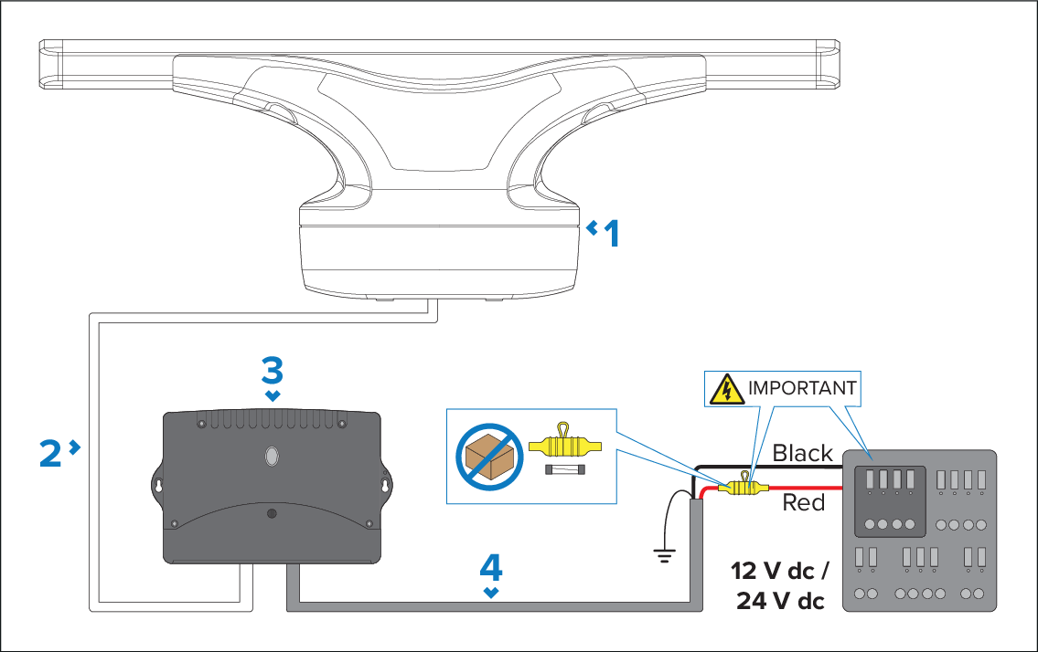
Radar scanner.
Power cable (Part number: A80653).
VCM100 power converter.
Power cable from vessel power supply to VCM100 (power cable not supplied).
Vessel power supply.
The radar scanner is intended for use on vessel DC power systems operating at 12 or 24 Volts DC.
All power connections must be made via the VCM100 Voltage Converter Module.
The radar scanner must NOT be connected directly to a battery.
The radar scanner’s power cable must be connected directly to the VCM100 only.
Only one radar scanner must be connected per VCM100 unit. Each radar scanner in your system requires a dedicated VCM100 unit.
The power connection between the radar scanner and the VCM100 must be via an official Raymarine power cable (a power cable is supplied with the radar).
Do NOT cut and re-join any part of the power cable. A range of cable lengths are available for longer cable runs (refer to Spares and accessories).
The maximum length for the radar power cable (including all extensions) is 25 m (82 ft).
The radar scanner must be connected to the POWER OUT terminals of the VCM100 .
The screen (drain) strands of the radar scanner's power cable must be connected to one of the VCM100 SCREEN terminals.
The following diagram illustrates the power connections of the supplied power cable.
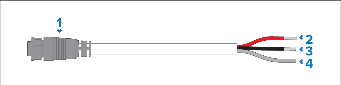
Power connector
Red wire — connect to the positive POWER OUT terminal of the VCM100.
Black wire — connect to the negative POWER OUT terminal of the VCM100.
Screen (drain) strands — connect to one of the SCREEN terminals of the VCM100.
Fuses (not supplied) are required for circuit protection for the radar scanner. For information, refer to the fuse ratings listed below.