Power distribution
The product is supplied with a power cable, either as a separate item or a captive cable permanently attached to the product. Only use the power cable supplied with the product. Do NOT use a power cable designed for, or supplied with, a different product.
Refer to the Power connection section for more information on how to identify the wires in your product’s power cable, and where to connect them.
See below for more information on implementation for some common power distribution scenarios:
When planning and wiring, take into consideration other products in your system, some of which (e.g. sonar modules) may place large power demand peaks on the vessel’s electrical system, which may impact the voltage available to other products during the peaks.
The information provided below is for guidance only, to help protect your product. It covers common vessel power arrangements, but does NOT cover every scenario. If you are unsure how to provide the correct level of protection, please consult an authorized dealer or a suitably qualified professional marine electrician.
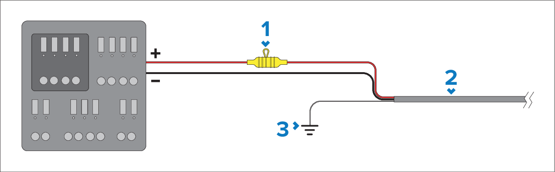
Implementation — connection to distribution panel (Recommended)
| PowerConnection to distribution panel | Description |
|---|---|
1 |
If not supplied already fitted to the power cable, a waterproof fuse holder containing a suitably-rated inline fuse must be fitted. For suitable fuse rating, refer to: Inline fuse and thermal breaker ratings. |
2 |
Product power cable. |
3 |
Ground wire connection point. |
ConnectionsDistribution panelPowerDistribution panelIt is recommended that the supplied power cable is connected to a suitable breaker or switch on the vessel's distribution panel or factory-fitted power distribution point.
The distribution point should be fed from the vessel’s primary power source by 8 AWG (8.36 mm2) cable.
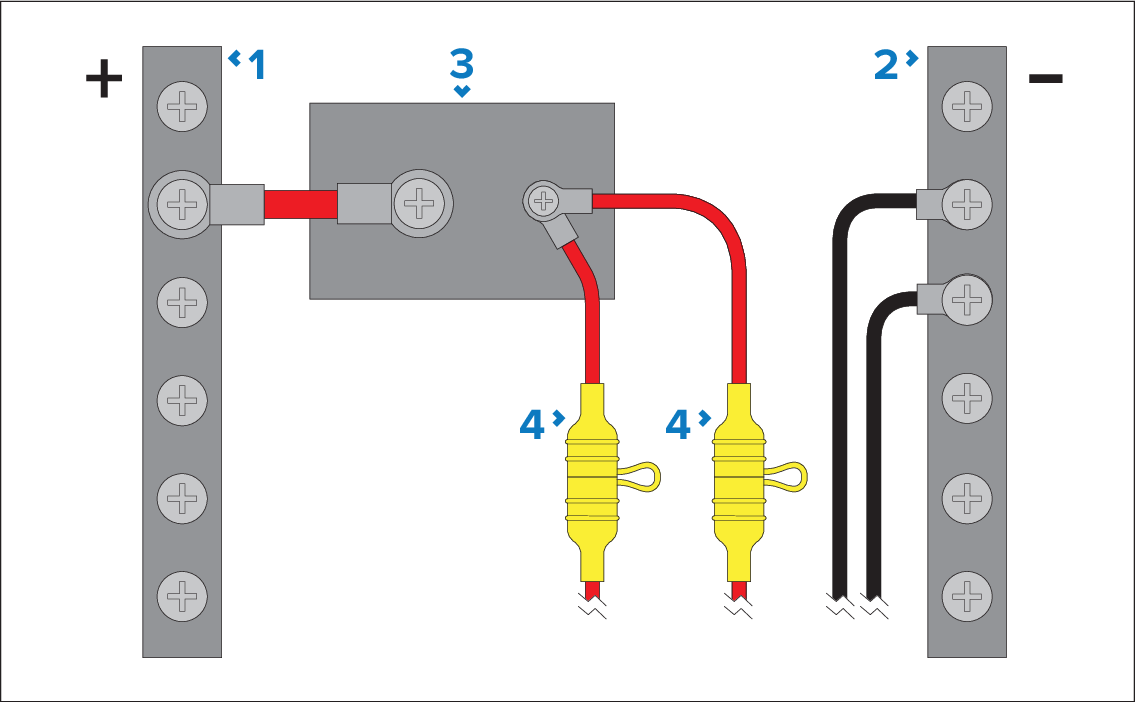
PowerSharing a breakerIdeally, all equipment should be wired to individual suitably-rated thermal breakers or fuses, with appropriate circuit protection. Where this is not possible and more than 1 item of equipment shares a breaker, use individual inline fuses for each power circuit to provide the necessary protection.
The power cable supplied with your product includes a separate ground wire, which must be connected to the vessel’s common RF ground. For more information, refer to: Power cable ground wire connection
| PowerSharing a breaker | Description |
|---|---|
1 |
Positive (+) bar |
2 |
Negative (-) bar |
3 |
Circuit breaker |
4 |
If not supplied already fitted to the power cable, a waterproof fuse holder containing a suitably-rated inline fuse must be fitted. For suitable fuse rating, refer to: Inline fuse and thermal breaker ratings. |
Observe the recommended fuse / breaker ratings provided in the product’s documentation, however be aware that the suitable fuse / breaker rating is dependent on the number of devices being connected.
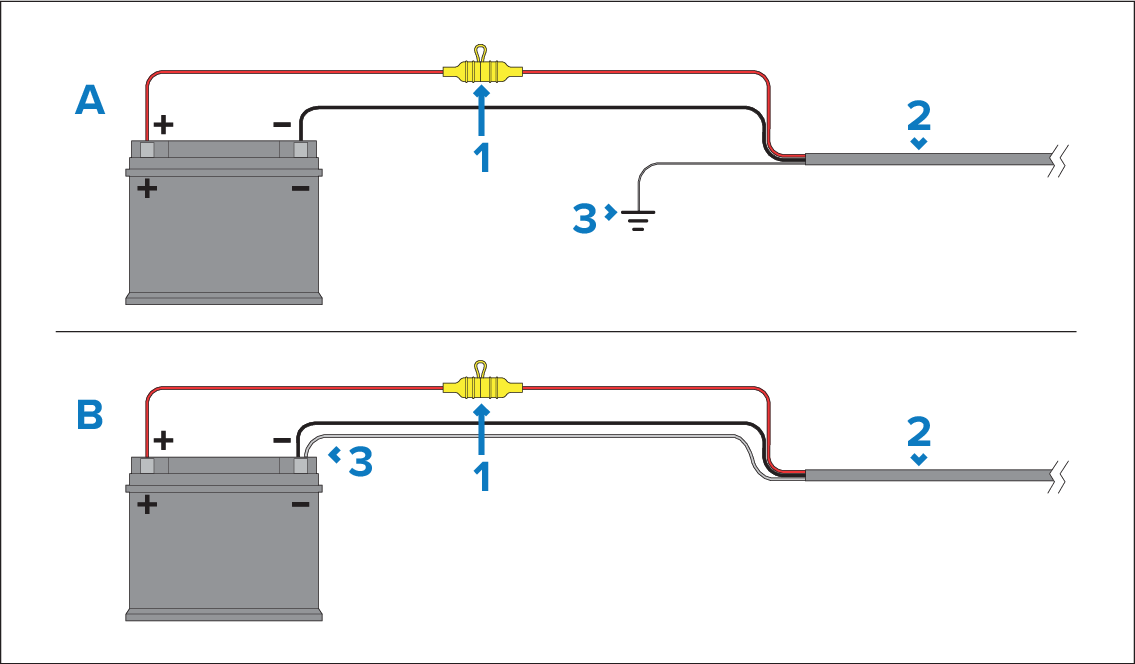
Implementation — direct connection to battery
ConnectionsBatteryPowerBattery connectionWhere connection to a power distribution panel is not possible, the power cable supplied with your product may be connected directly to the vessel's battery, via a suitably rated fuse or breaker.
The power cable supplied with your product includes a separate ground wire, which must be connected to the vessel’s common RF ground (if available), or the battery’s negative terminal. For more information, refer to: Power cable ground wire connection
If the power cable is NOT supplied with a fitted inline fuse, you MUST fit a suitably rated fuse or breaker between the red wire and the battery’s positive terminal.
Refer to the inline fuse ratings provided in the product’s documentation.
If you need to extend the length of the power cable supplied with your product, ensure you observe the dedicated Power cable extensions advice provided in the product’s documentation.
| PowerConnection to battery | Description |
|---|---|
1 |
If not supplied already fitted to the power cable, a waterproof fuse holder containing a suitably-rated inline fuse must be fitted. For suitable fuse rating, refer to: Inline fuse and thermal breaker ratings. |
2 |
Product power cable. |
3 |
Ground wire connection point. |
Battery connection scenario A:
Suitable for a vessel with a common RF ground point. In this scenario, the power cable’s ground wire should be connected to the vessel’s common ground point.
Battery connection scenario B:
Suitable for a vessel without a common grounding point. In this case, the power cable’s ground wire should be connected to the battery’s negative terminal.
Grounding
PowerGrounding
The power cable supplied with your product includes a separate ground wire, which must be connected to the vessel’s common RF ground (if available), or negative battery terminal. For more information, refer to: Power cable ground wire connection
Ensure that you also observe any additional grounding advice provided in the product’s documentation.
More information
InstallationBest practiceIt is recommended that best practice is observed in all vessel electrical installations, as detailed in the following standards:
BMEA Code of Practice for Electrical and Electronic Installations in Boats
NMEA 0400 Installation Standard
ISO 13297: Small craft — Electrical systems — Alternating and direct current installations
ISO 10133: Small craft — Electrical systems — Extra-low-voltage d.c. installations
ABYC E-11 AC & DC Electrical Systems on Boats
ABYC A-31 Battery chargers and Inverters
ABYC TE-4 Lightning Protection